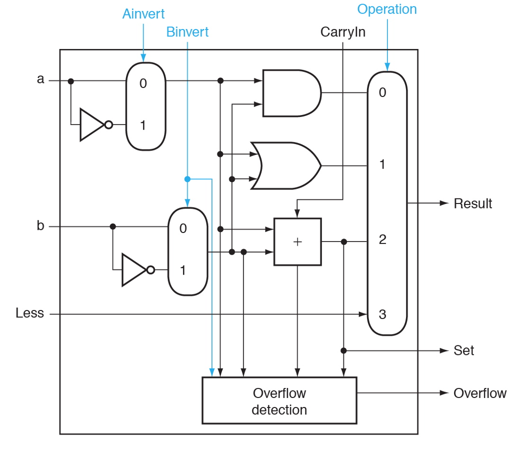


Op Code Operation ADD SUB AND ORR ALU Control bits 00 01 10 11 Status effects N, Z, C, V N, Z, C, V N. Hint: use a decode of the control bits to conditionally create the 2-s complement of an operand.Ĭontrol inputs There are a large number of possible control inputs on a complete ARM ALU. 3 Abstract Aim of the project is to design a 4-bit ALU to perform seven arithmetic operations and four logic operations. Be sure that your design uses no more than one adder. Heres what I have so far but Im stuck with what to do for the f values for the last two and whether the if statement syntax is correct. The input signal Op is a 3 bit value which tells the ALU what operation has to be.
4b110:za<<1 //if sel6, Shift a left by 1 bit 4b111:za>1. In this article I have shared Verilog code for a simple ALU.Table of 32-bit Arithmetic Logic unit 19. Result is negative Z Result is zero с Result is carry out Result is overflow An adder is a relatively expensive piece of hardware. So in my earlier posts, I explained how to design an ALU using VHDL. I have conformed to the norms and guidelines given in the Ethical Code of Conduct. Now you can take up the 1 bit ALU as block and construct a 4 bit ALU. The four flags are as follows: ALUFlag bit name Meaning N. An arithmetic logic unit (ALU) is a digital circuit used to perform arithmetic and. timescale 1ns / 1ps module alu ( a, b, sel, en, y ) input 3:0 a, b input 3:0 sel input en output reg 7:0 y always () b. It should have the following module declaration: module alu (input logic (31:0] a, b, input logic (1:0] ALUControl, output logic (31:0] Result, output logic (3:0] ALUFlags) The four bits of ALUFlags should be TRUE if a condition is met. Transcribed image text: SystemVerilog code Create a 32-bit ALU in System Verilog.


 0 kommentar(er)
